Sheet Metal Tab And Slot Design Guide
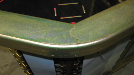
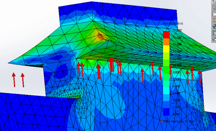
Consider the embossed hat section with a 0.500-in. Flat section, a 0.200-in. Height, and a 45-degree emboss angle, as shown on the left in Figure 1.It’s simple to draw on a computer, but it’s impossible to manufacture out of a single piece of sheet metal.
- Sheet Metal Tab And Slot Design Guidelines
- Sheet Metal Tab And Slot Design Guide Free
- Sheet Metal Tab And Slot Design Guide Pdf
- Because sheet metal products have a history of being designed by the guy who actually does the work on the floor, sheet metal products (think HVAC ducting, as well as the lockers in your gym) tend to be excellent examples of design for assembly, especially when looking at self-locating parts, which reduce assembly errors.
- We will focus on the flange method, where a sheet metal part is created in the formed state using specialized sheet metal features. To begin we first want to turn on the Sheet Metal tab on the CommandManager. To do this we simply need to right-click any tab on the CommandManager and select Sheet Metal from the drop down menu.
- When using slots and tabs the maximum width of the slot must be greater than the thickness of the tab and the tab length should equal the material thickness. Tabs The minimum width is equal to two times the material thickness or 3.200 mm, whichever is greater, while the maximum length is five times the width.
- I make a lot of weldments and sheet metal parts that are 12ga to 1/2in thk, I use 1/32' per side for the slot. Be mindfull if you have tabs on adjacent bends, when the part is bent wrong it may or may not fit in all of the slots anymore.

Sheet metal design guidelines are followed to design quality sheet metal enclosures. This helps in delivering the product at low cost and faster timelines. All

Sheet Metal Design Guidelines

Following points should be considered during the design of sheet metal parts for press bending.
Sheet Metal Material Selection
- Simulation Studies
- Past Experience
- Reverse Engineer existing products
- Experimental Studies
Read this guide to know more about sheet metal material selection Process.
Minimum inside bend Radius for Sheet Metal Parts
Sharp inside bend radius in sheetmetal parts can cause material flow problems in soft material and fracturing in hard material. Which results in localized necking or fracture. Therefore sharp bend radius is not recommended in sheet metal parts.
Bend radius throughout the sheet metal part is kept constant to take the advantage of using the same tool during manufacturing.
Minimum Sheet Metal Bend Length Recommendations

Minimum Hole Diameter Guidelines
Hole/Slot Distance from Bend Edge
Minimum distance between hole/slot edge to bend edge is recommended to avoid metal distortion, deformation and fracturing.
Center to Center Distance Between two Holes
Minimum center to center distance between two holes in sheet metal parts is required to avoid metal distortion, deformation and fracturing.
Recommended Minimum distance between two hole centers in sheet metal design should be equal to sum of hole radius plus two times the sheet thickness.
Recommended Distance = Radius of Hole1 + Radius of Hole2 + Sheet ThicknessEffect of Grain Direction in Sheet Metal Bending
During sheet metal processing ( rolling operation), material grains are arranged in the direction of rolling. When Sheetmetal is bend perpendicular to rolling direction grain rearranges. That has negligible impact on part strength. Whereas bending parallel to rolling direction can lead to cracks because of destruction in grain structure.
Bend Relief in Sheet Metal Bend
Bend relief is provided at the end of the bending edge in sheet metal design to avoid any crack tearing in the corner. Relief height is generally kept greater than two times of sheet thickness plus bend radius.
Extrude Hole Size and Position Guidelines
Creating an extruded hole using a punching process requires extreme pressure/Force. Extruded holes very close to the part edge can lead to sheet metal deformation or tearing. Therefore the minimum distance between the extruded hole to edge if maintained.
Sheet Metal Tab And Slot Design Guidelines
Extruded hole to part edge (B) = 3T + D/2Center of extruded Holes (A) = (5 + Hole Dia + 2T)Extruded Hole and bend edge (C) = 3T + R + D/2Sheet Metal Tab And Slot Design Guide Free
Round Emboss Design Guidelines
Creating Emboss feature using sheet metal punching requires extreme pressure. Very close emboss to the part edge, can lead to deformation in the sheet metal part.
A – Distance From Emboss To part Edge = 3T + D/2B- Distance Between Two Emboss = (5 + D)C- Distance between Emboss and Sheet Metal bend = 3T + R + D/2Dimple Feature Design in Sheet Metal Parts
Louver Feature Design in Sheet Metal
Minimum distance between louver feature and bending edge is maintained to avoid metal deformation.
(P1) Distance Between Two lowers on Shorter Edge = 5 mm(P2) Distance Between Two lowers on Longer Edge = 8 mmRound Knockout Design Recommendation
Folding and adding bending tabs is one of the easiest and most economical way of making moderately strong joints in sheet-metal parts that will permanently or semi-permanently attach to one another. It requires no screws, rivets, or other pieces of fastening hardware.
There are few limitations on fastening tabs. The metal tabs that are to be bent should be between 0.12 and 0.8 in. thick. And the metal should have the ductility to stay in place and not spring back after being bent. The metals most commonly joined using tabs are soft steel, aluminum, copper, and brass.
Sheet Metal Tab And Slot Design Guide Pdf
For the best results, parts should be designed to bend perpendicularly to the direction of sheet rolling, or at least 45 deg. from that direction. Also, the stamping burr should be at the inside of the bend when possible. The final bend should be made in the same direction as the preliminary bend.